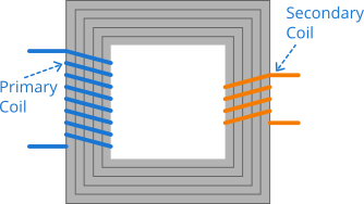
A transformer is an electronic device that allows you to change or transform the voltage or current. It can also be used to transform the impedance. In transmission lines, high voltage and low current are transferred to minimize the \(i^2R\) loss in very long wires, but that high voltage is not suitable for typical household use, and the voltage must be decreased to serve in the households.
A step up transformer is used to convert low voltage to high voltage and supplied with the transmission lines. The high voltage must be decreased to serve in the household. The transformer in the area decreases the voltage typical for household use and served to the households.
A transformer consists of two solenoid type coils and a common core (magnetic material) such as iron. One coil connected to the main power source is called primary coil and another connected to the load (for example connected to a house) is called secondary coil. Both coils are wrapped in the same iron core, so that the flux in one coil is entirely linked to the other coil, and the emf induced per turn on either coil is the same.

As a consequence of Faraday's law, the emf induced in the primary coil is
\[\mathcal{E}_1 = - N_1\frac{d\Phi_B}{dt}\tag{1} \label{1}\]
where \(N_1\) is the number of turns in the primary coil, and similarly if \(N_2\) is the number of turns in the secondary coil, the emf induced in the secondary coil is
\[\mathcal{E}_2 = -N_2\frac{d\Phi_B}{dt} \tag{2}\label{2}\]
Note that the emf induced per turn in both coils is the same that is \(d\Phi_B/dt\) and it is due to the proper flux linkage between the coils. We consider the resistance of both coils to be negligible, so the terminal voltages are equal to the emfs. Therefore,
\[\frac{V_2}{V_1} = \frac{N_2}{N_1}\tag{3} \label{3}\]
The primary circuit is the one where power source and primary coil are connected together, and the power is supplied to the primary coil. The load and secondary coil are connected together in secondary circuit, and power is delivered to the secondary circuit.
If \(N_2 > N_1\), the transformer is called step up transformer, and in that case, voltage \(V_2\) is greater than the voltage \(V_1\), and if \(N_2 < N_1\), the transformer is called step down transformer and the voltage \(V_2\) is less than \(V_1\).
In terms of power consideration, the power supplied and delivered is the same in both circuits, that is the power in primary circuit is the same as the power in secondary circuit. If \(I_1\) is the current in primary, and \(I_2\) in secondary, the power relationship tells us
\[I_1V_1 = I_2V_2 \tag{4}\label{4}\]
The above equation tells us that, as the voltage increases in the secondary circuit, the current decreases, that is
\[I_2 = \frac{V_1}{V_2}I_1 \tag{5}\label{5}\]
And that's what we do to transfer power in long transmission lines. We increase the voltage by a step up transformer thereby decreasing the current to minimize the \(i^2R\) loss, and power remains the same. Then we decrease the voltage to serve to the consumers.
You can use transformers not only to transform voltage and current but also to transform the resistance. In the secondary circuit, \(I_2 = V_2/R\), and using this value to eliminate \(I_2\) in Equation \eqref{4} and further eliminating \(V_2\) using Equation \eqref{3} and solving, you get
\[\frac{V_1}{I_1} = \frac{R}{(N_2/N_1)^2} \tag{6}\label{6}\]
The value \(V_1/I_1\) is the equivalent resistance of the circuit, that is this value is the ultimate load resistance when viewed from the primary circuit. It means you can match the source and load resistance for the delivery of the maximum power. The maximum power transfer theorem states that, the power transfer is maximum if the source resistance matches the load resistance. The process of matching the source and load impedance is called impedance matching.


