The resonance also takes place in electrical circuits similar to the mechanical resonance in Mechanics. The mechanical resonance occurred when the frequency of driving force was equal to the natural frequency of the oscillating system.
Here we are achieving the electrical resonance in RLC series circuit. You know the fact that if the driving frequency is equal to the natural frequency, the phenomenon of resonance takes place. What's the natural frequency in RLC circuit? We know in LC circuit that the current oscillates on its own with a particular frequency, and we call that frequency the natural frequency.
Here in this case we have the driving frequency and we make sure that the driving frequency is equal to the natural frequency (without resistance) with resistance present to obtain the resonance. We know that both inductive and capacitive reactances depend on the frequency, that is \(X_L = L\omega\) and \(X_C = 1/C\omega\).
The inductive reactance increases and the capacitive reactance decreases as the frequency increases. For a given inductance and capacitance, the inductive and capacitive reactances are equal at a frequency called resonance frequency, and this resonance frequency is equal to the natural frequency. You know the impedance of RLC series circuit is \(Z = \sqrt{(X_L - X_C)^2 + R^2}\). When \(X_L = X_C\), \(Z = R\), and it is the same as there is no capacitor and inductor!
At resonance, \(X_L = X_C\), that is \(\omega_0\,L = 1/\omega_0\,C\) and this gives \(\omega_0 = 1/\sqrt{LC}\), and this is the angular frequency of the oscillating current in LC circuit. This shows that the frequency without damping is the natural frequency or the resonance frequency. The frequency with damping is called damped frequency or sometimes referred to as damped natural frequency.
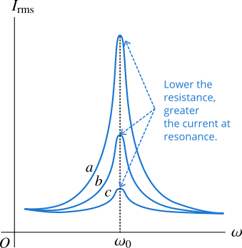
When the driving frequency equals the natural frequency the phenomenon of resonance takes place with minimum impedance, and therefore the current is maximum at resonance frequency. The Figure 1 shows the current peaks at resonance in RLC series circuits.

The curves \(a\), \(b\) and \(c\) have different current peaks at resonance. It is because the each curve is for the different value of resistance. The resistance for the curve \(c\) is greater than that for \(b\), and the resistance for \(b\) is greater than that for \(a\). The greater the resistance, the lower the peak, and the less the resistance, the higher the peak.
You know that the voltage across an inductor always leads the current by \(90^{\circ}\) and the capacitor voltage lags the current by \(90^{\circ}\), therefore these two voltages are at phase difference of \(180^{\circ}\). At resonance, the two voltages are equal and opposite and they cancel each other. Therefore, at resonance the circuit behaves like there is no inductor and capacitor, and the source voltage appears across resistance only.
We can also change the frequency by changing the inductance or capacitance. This is how radio receivers circuits are developed. You can change either the capacitance by sliding a overlapping plate or inductance by sliding the magnetic material outside or inside the inductor coil. Doing this changes the natural angular frequency \(1/\sqrt{LC}\) and can receive this angular frequency by the radio transmitter. The natural frequency \(f_n\) is related to natural angular frequency \(\omega_0\) by the relationship, \(f_n = \omega_0/2\pi\).


