Here we learn what happens if an inductor is placed in a circuit with sinusoidally changing source of emf and how the voltage and current change.
Effect of inductor in AC circuit
What is the effect of inductor in AC circuit? The answer is inductive reactance.
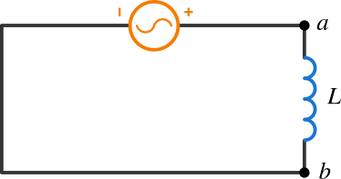
In Figure 1 an inductor is connected with a source of emf that varies sinusoidally. The sinusoidally changing current is
\[i = I\sin(\omega\,t) \label{1} \tag{1}\]
You know that the voltage across an inductor is \(Ldi/dt\). In Figure 1, as the current increases in the inductor, \(di/dt\) is positive and the voltage is positive, that is the potential of point \(a\) with respect to point \(b\) is positive.

We know the expression from self inductance, the induced emf is \(\mathcal{E} = -Ldi/dt\), which is negative of the voltage across the inductor. This direction is in the direction of current. The voltage across the inductor at any instant is
\[v = L\frac{di}{dt} = IL\,\omega\cos{\omega\,t} = IL\,\omega\sin(\omega\,t + \frac{\pi}{2}) \tag{2} \label{2}\]
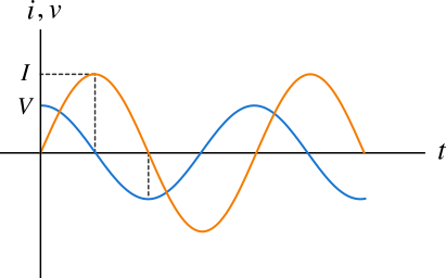
You can see from the above Equations \eqref{1} and \eqref{2} that the current and voltage are out of phase by \(\pi/2 \, \text{rad}\). Let's look at the curves of both current and voltage as a function of time shown in Figure 2 below.

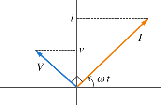
From the curves, you can seen that when the current is zero, voltage is maximum and vice versa. The phasor diagram below shows that the voltage leads the current by \(90^{\circ}\). The projections determine the instantaneous values of corresponding quantities.

In Equation \eqref{2}, you can see the term \(IL\,\omega\). You know that the current, voltage and resistance are related by the relationship \(V = IR\). The product \(L\omega\) has the SI unit Ohm (\(\Omega\)) and therefore plays the role of resistance in the circuit called inductive reactance \(X_L\). The inductive reactance is
\[X_L = L\omega \tag{3} \label{3}\]
Since the inductor always opposes the change in current, it acts as some sort of resistance to the circuit and this exits only when the current is changing. The expression of the inductive reactance shows that it depends on the angular frequency and inductance. The greater the angular frequency, the greater the inductive reactance.
In terms of rms value, the voltage across the inductor is \(V_\text{rms} = I_\text{rms}\omega\,L\), this implies \(I_\text{rms} = V_\text{rms}/L\omega\). The greater the angular frequency, less the rms current. So, inductors can be used to filter high frequencies, and such filter are called low pass filters allowing only low frequency, and low pass filter with inductor is called inductive low pass filter. Similarly capacitive high pass filter (capacitor in AC circuit) allows high frequency current and blocks low frequency or dc.


